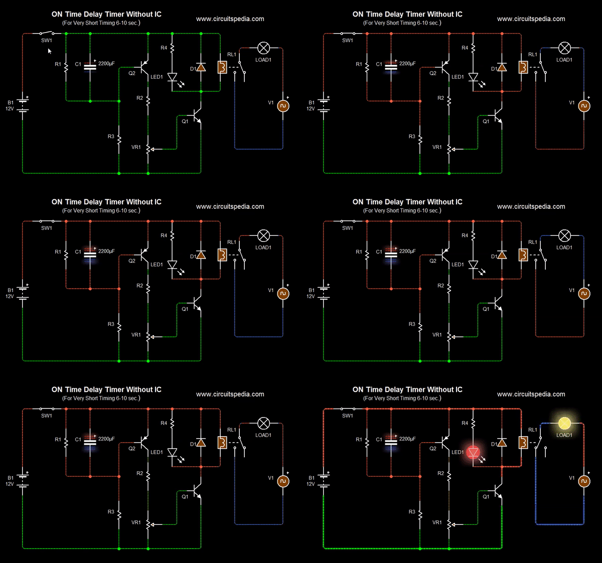
With toggle S-1 still connected, I'm waiting my 6 volt relay on. I'm wondering if this design is feasible for delays in the range of about 100 nanosecond to 10s of microsecond? Please advice, thanks.įollowing your notes, I put R-1 = 50 ohm and C-1 = 10 microFarad to get timer on about 7 minutes after connecting toggle S-1 ( 50x10x0.85 = 425 seconds, equal to 7 minutes plus). I'm a 3rd year student looking to build a simple variable delay circuit to delay continuous pulses to LEDs from an arbitary waveform generator. very urgent.Ģ, To calculate the time delay, use the equation R1 * C1 * 0.85=T, where R1 is the value of R1 in Ohms, C1 is the value of C1 in uF, and T is the time delay in seconds. and cnaging capacity of r and C makes no changes on interwal.Ģ second on and 3minutes off countinious working timerĭear Sir, I want to curcuit for 2sec on and 3 min off time contionuesly working type curcuit. When ever power on a relay switch on after 8 hours I need a time delay relay for 8 hours.(12 v DC or 230 v AC) (Editor's notes: See the 556 timer IC datasheet.) I am using a Digital Safe and when the circuit is activated the output pullsdown a 6 volt solenoid - Problem is the output pulse is only 1 second - Needs to be 6 or 7 seconds (Power supply is 6 volts and output to solenoid is 6 volts)Ĭircuits I have viewed seem to require 12 volts.Ģ second on and 2 minutes off countinious working timerĭear Sir, I want to curcuit for 2 sec on and 2 min off time contionuesly working type curcuit. If you use a large relay, you my need to add a transistor to the output of the circuit in order to drive the larger load.Īir Flow Detector, Wire Loop Alarm, Simple Two Speed Contactor DC Motor Controller, 7 Segment LED Counter, Simple Lie Detector, Low Voltage Alarm, Video Stabilizer/MacroVision Removal, Pulse Width Modulation DC Motor Control, Simple Polarity Tester, Pine Racecar Victory Judge, Rain Detector, Time Delay Relay, Time Delay Relay II, Stepper Motor Controller, Touch Switch, Video Activated Relay, Digital Keypad Combination Lock, AC Motor Speed Controller, Simple Servo Controller, Water Detector With Sump/Bilge Pump Controller, Simple Touch Switch

as soon as the voltage at transistor base Q1 is close to 0.7V, the transistor goes ON and motor goes OFF. On Power ON, The motor will be ON for a specific period of time and the time is decided by C1 Capacitor and R2 and RV1 Resistor. and i am operating a 24V 10 RPM AC Motor for one of my application. The power source is 24V 3 Amps Transformer.


I have built a timer circuit using Transistor.


 0 kommentar(er)
